Introduction
The application of shaking in papermaking machines has been popular for a long time, but the early shaking designs were based on installing a device on the ground that pushed and pulled the breast roller by mechanical structure. This design is obviously not scientific enough, with limited thrust and poor performance. This article discusses a new type of shaking equipment without reaction force. This shaking is more effective in improving paper including uniformity, banner, paper strength, etc., and has strong power, stable equipment performance and longer life.
The working principle of shaking
The working principle of shaking is: the shaking main equipment is connected to the breast roller to realize high-speed swing in the CD direction. When the pulp flow is injected into the net, the breast roller drives the net to swing horizontally to form a shearing effect on the pulp flow. On the one hand, it can effectively disperse the fiber clusters, so that more fibers can be interwoven and arranged to improve the uniformity; it can also change the arrangement angle of the fibers to improve the longitudinal and transverse tension ratio of the paper; similarly, the lateral swing can also make the points with quantitative deviations compensate each other, eliminate high points, supplement low points, make the banner uniformity better, and make the paper surface smoother.
At present, the most popular shaking in the world is basically a design that installs four sets of symmetrical counterweights with adjustable angles on the shaking trolley. The relative angles of the counterweights are controlled by additional equipment. The shaking trolley is directly connected to the breast roller through a connecting rod. The trolley runs to achieve CD-direction swing, thereby driving the breast roller to reciprocate in CD direction. This reaction-free design completely changed the design concept of early shaking. Early shaking trolleys were fixed on the ground on the transmission side, and special mechanical mechanisms were used to push and pull the breast roller. This would place very high requirements on the installation foundation of the shaking trolley, and the huge reaction force would frequently damage the shaking foundation. This latest form of reaction-free shaking has a longer life, greater thrust, more reliable performance, and a wider operating window.
Shaking equipment structure
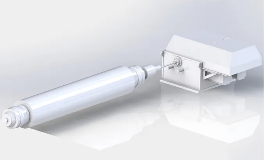
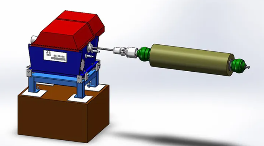
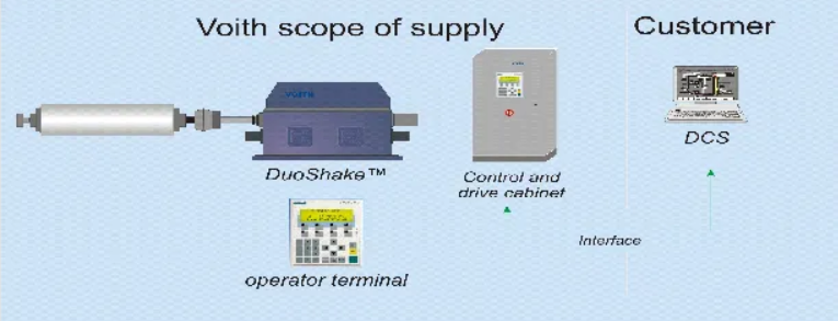
A set of shaking equipment is generally delivered with 2 breast rollers (one for backup and one for use), a shaking main unit, a separate control system, and some breast rollers may also be equipped with a separate breast roller bearing lubrication system. A control box is installed on site, and the operator can change the length and swing rate of the shaking swing by inputting the two parameters of amplitude and frequency. Generally speaking, the amplitude of the new shaking can reach more than 30mm, and the maximum frequency can reach 10Hz.
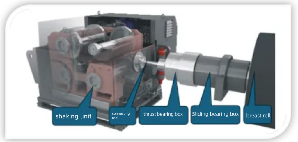
In order to ensure that the breast roller is lightweight and has high structural strength, the roller shell is generally made of carbon fiber material, and the surface of the roller shell is covered with a rubber layer to ensure wear resistance. The sliding bearings at both ends of the breast roller are sleeved on the shaft head, and the sliding bearing box is installed on the frame. The end of the roller transmission side is also installed with a complex back-to-back thrust bearing set to ensure that the breast roller can be pushed by the breast roller connected to the shaking unit through a connecting rod, and can move in a circle and swing back and forth to transmit sufficient thrust.
Design of the shaking unit
The shaking unit is one of the most complex and important shaking equipment. At present, the most popular shaking unit design in the world is a design with four sets of counterweights installed symmetrically and with adjustable angles. The following figure is a schematic diagram of the structure of the four counterweights working together:
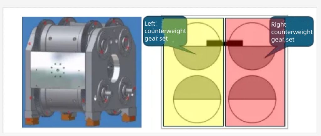
The yellow in the figure is the left counterweight gear set: the upper and lower sets of counterweights on the left are fixed on the upper and lower gears respectively, the two gears are meshed and rotate in the positive direction, the upper and lower counterweight angles are always symmetrical, and the centrifugal forces generated in the upper and lower directions are offset after operation, and the lower spindle is connected to a servo motor.
The red in the figure is the right counterweight gear set: the upper and lower sets of counterweights on the right are fixed on the upper and lower gears respectively, the two gears are meshed and rotate in the opposite direction, the upper and lower counterweight angles are always symmetrical, and the centrifugal forces generated in the upper and lower directions are offset after operation, and the lower spindle is connected to another servo motor.
The left and right counterweight gear sets are fixed on the frame, and the frame with the counterweight gear sets is collectively called the shaking trolley. When the counterweights on the left and right sides rotate completely symmetrically, the centrifugal forces inside the trolley offset each other, and the trolley will not have any up and down or left and right movement. The two gear sets of the shaking trolley are driven by two main motors.
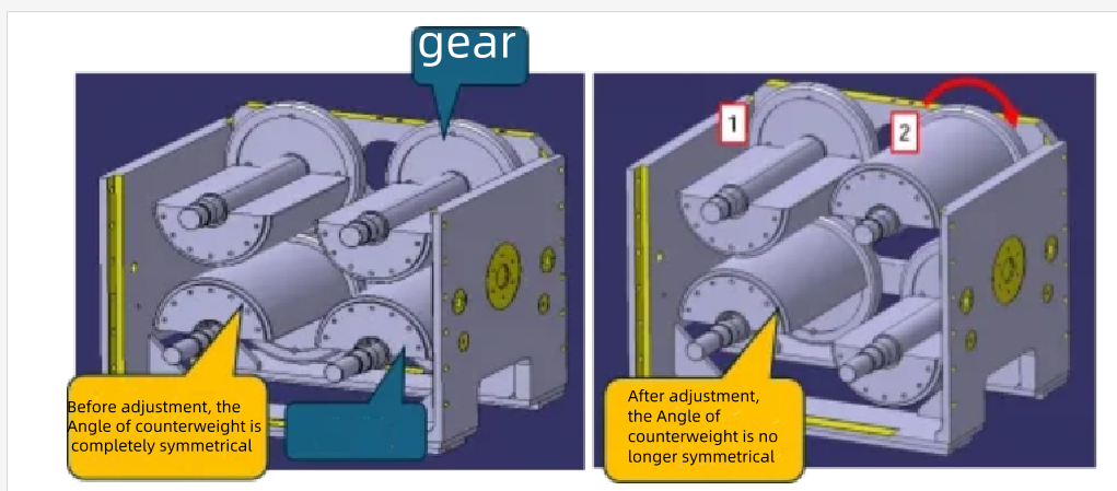
At present, the most common method is that two main motors cooperate with encoders for phase angle control. There is an angle encoder at the rear end of each motor to detect the relative position of the two motor spindles. When amplitude is not required, the two sets of four counterweights are completely symmetrical.
After the shaking is set to the required frequency and stroke command requirements (for example, set to 8Hz, stroke 20mm), the two servo motors start to rotate and reach the required speed (8Hz, 480 rpm), and then start to adjust the phase angle. The left counterweight servo motor is adjusted clockwise and the right counterweight servo motor is adjusted counterclockwise. The trolley starts to swing left and right. After the position sensor on the trolley detects that the trolley position has reached the set stroke value, the two motors stop adjusting the relative angle (the two motors still run at high speed during the adjustment process).
There are sliding tracks and shoes at the bottom of the shaking trolley. The shoes are made of copper. The shoes are embedded or stuck in the track. There is pressurized lubricating oil inside the track. When the hydraulic system is started, high-pressure lubricating oil is sprayed out of the track. An oil film is formed between the trolley shoes and the track. The trolley is suspended on the oil film, and the track and the shoes are basically not worn (the trolley generally has four shoes and four supporting tracks at the four corners. In order to ensure the pressure of the lubricating oil, the track is generally designed with a small-caliber nozzle inside to ensure that the pressure at each suspension point is balanced).
The other side of the shaking trolley is directly connected to the breast roller through a connecting rod. A quick disassembly and assembly chuck is also designed at the position where the connecting rod connects to the breast roller to facilitate disassembly and assembly when changing the net and dropping the breast roller.
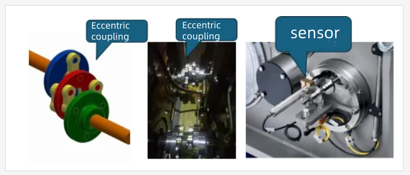
In addition, there is a more special mechanism, which is the eccentric coupling. The two main motors are connected to the counterweight spindle through the coupling. After the shaking operation, the trolley swings back and forth, and the main motor needs to continuously transmit the torque to the spindle. This requires the coupling to transmit torque and allow a large position deviation, just like the principle of the universal joint coupling. However, the eccentric coupling here is more compact and requires higher installation and centering accuracy.
Shaking effect evaluation
The evaluation index of the shaking effect is mainly the shaking index. The shaking index is directly proportional to the square of the shaking frequency and the amplitude, and inversely proportional to the speed of the paper machine:
SKZ=N2*S/V.
The improvement effect of frequency on shaking is a square increase, and the improvement effect of amplitude is only a linear increase. Therefore, if you want to improve the uniformity, increasing the frequency will have a more obvious effect, but there is no doubt that the energy consumption will increase more obviously. The larger the shaking index, the better the uniformity improvement effect. Generally, the higher the grammage and the greater the concentration, the easier it is for fibers to flocculate and the evenness to deteriorate. Shaking, especially for paper with high grammage, has a better improvement effect. For paper with a basis weight of 60 to 70gsm, the effect of shaking on the formation is not obvious, but for paper with a basis weight of more than 150gsm, the effect is more significant.

Other components of the shaking system
The above are some key components and working principles of the shaking system. Of course, in addition to the above components, a complete and scientifically designed shaking system must also include a complete hydraulic system to lubricate all lubrication points, including gear meshing, bearings, couplings and trolley suspension. There must also be a cooling system to cool the hydraulic system. The shaking box must also be equipped with necessary electrical detection components to detect the trolley position and feedback to the system. It must also include trolley centering return springs, emergency phase angle return to zero position and other components. More details will not be repeated here.
The fault diagnosis and analysis of shaking and problem handling will be discussed separately in another article later.