The headbox is the “heart” of a paper machine. The headbox lip area is the key link between the “heart” and the “artery”.
Parameters of the headbox lip area
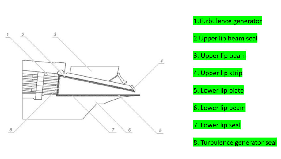
The parameters of the headbox lip area (i.e. the weir area) include lip opening, lip horizontal position, upper lip extension distance, spraying distance, spraying angle, lip and breast roll gap, etc.
(Note:
The lip opening curve is not within the scope of this discussion. The lip opening curve and lip opening are different concepts.)
The above parameters are the most common parameters that need to be adjusted in paper mills. Through the discussion of the above parameters, it can be concluded that adjusting the headbox can produce high-quality qualified paper more scientifically and reasonably, reduce waste, and improve the operation efficiency of the paper machine.
Therefore, we will first introduce the basic meaning of the relevant parameters, and then explain the practical significance of these relevant parameters in detail.
Detailed explanation of main parameters
The lip opening
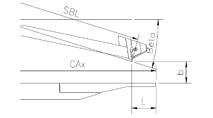
Which is also called the lip vertical position, refers to the distance between the upper and lower lip plates (the b value shown in the figure below).
The lip opening of general suppliers is about 5-100mm, and the opening of conventional production operations is generally between 5-20mm.
The size of the lip opening plays a vital role in the basic performance of paper.
The lip opening is generally operated by process personnel, and the action of the lip is the up and down action of electrical and mechanical equipment acting on the upper lip plate as a whole to control the distance of the pulp outlet. This refers to the size of the gap between the upper and lower lips in the vertical direction. The change in the lip opening will directly affect the amount of sizing and water supply, thereby changing the key parameters of paper such as uniformity and moisture.
When the paper machine is running stably, the result of the headbox lip pressure reduction is that the amount of sizing and water supply (the absolute dry amount remains unchanged, and the amount of water supply decreases), which will reduce the dehydration load at the rear end, but the fibers are more likely to flocculate, causing the paper uniformity to deteriorate.
Of course, the low lip pressure can not only reduce the amount of water supply and improve the dehydration effect, but also make it easier to retain fine fibers, making the paper surface more delicate, and increasing the retention rate and reducing consumption.
In addition, the low headbox lip pressure will also interfere more strongly with the fiber arrangement, allowing more fibers to be arranged in the MD direction, which will indirectly change the longitudinal and transverse paper performance.
Too low a lip opening will make the fibers more likely to flocculate, thereby deteriorating the uniformity, and too small a lip opening will make it easier to form pulp channel and other spraying abnormalities.
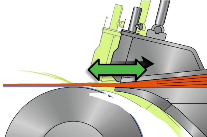
The lip horizontal position
refers to the relative distance of the upper lip plate lip opening in the horizontal direction relative to the lower lip plate slurry outlet, as shown in the figure below.

The horizontal movement range of the general supplier is between -20 and +50mm. The conventional operating position depends on the production. The horizontal position of the lip plate is generally operated by the process personnel. The horizontal movement of the lip plate is completed by the motor reducer driving the upper lip plate or the lower lip plate to move forward and backward.
Most of the headbox suppliers design the horizontal movement of the headbox lip plate to control the touch point by moving the upper lip plate forward and backward. Only some of the headbox designs of VOITH use the lower lip plate to move forward and backward to control the touch point position.
The horizontal movement of the upper lip of the headbox will directly affect the distance of the pulp jet, which is what we call the flying pulp length, and the pulp landing point is what we often call the touch point. Under normal circumstances, the touch point is most suitable at the front edge of the forming board.
- If the touch point is too long, if it falls on the forming board, it is easy to bring in air bubbles, resulting in holes and paper defects on the paper. However, in this case, the dehydration is delayed, which will help improve the uniformity.
- If the touch point is too short and falls on the breast roller or the gap between the breast roller and the forming board, the dehydration will be too intense, which may cause flying pulp, poor uniformity, excessive loss of fine fibers, and poor paper surface.
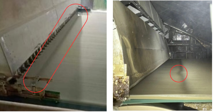
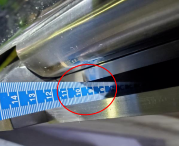
Neat touch points& Uneven touch points
When the paper machine speed is low because the pulp pressure is low, the distance of pulp flow injection will be closer, so at this time, the upper lip plate needs to be pulled back. If the upper lip plate moves backward, the touch point will be longer, thereby ensuring that the pulp landing point is always on the front edge of the forming board. After the paper machine speeds up, the jet becomes longer and has to be operated in the horizontal direction, moving the upper lip forward to ensure that the screen dots remain unchanged.
Headbox spray angle and spray length
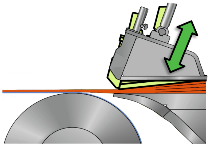
The spraying distance refers to the distance from the slurry flying off the lip to falling into the mesh table. As described by the green arrow in the figure below.
Theoretically, the shorter the spraying length of any headbox, the better the uniformity of the paper will be. This is because when the pulp flow passes through the step diffuser and the bleaching sheet inside the headbox, micro-turbulence will be formed, which will significantly break up the flocculated fiber clusters. Only after leaving the turbulence generator and the bleaching sheet flies away from the lip will the flocculation phenomenon begin to occur again.
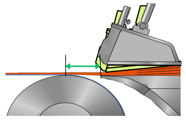
The spraying angle is formed by the line connecting the slurry from the lip separation to the mesh falling into the mesh, as shown in the figure below. The angle between the red arrow and the green arrow:
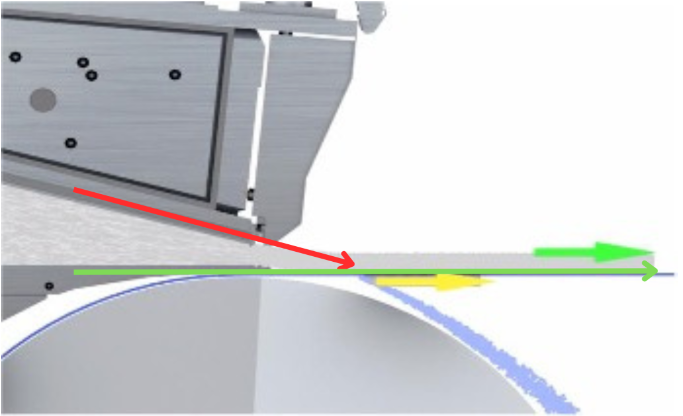
The definition of the headbox spray angle is the angle between the spray line and the mesh line. Theoretically, the smaller the spray angle, the easier it is for the fibers to be arranged horizontally. More fibers arranged horizontally will form more interlaced arrays of fibers, thereby improving the strength of the paper.
Although the dewatering element will slightly improve the occurrence of flocculation after the pulp flow falls into the mesh surface, its effect is minimal compared with the dispersion effect of the turbulence generator and the bleaching sheet.
Therefore, the distance from the pulp flow to the mesh surface from the lip is the time for fiber flocculation to occur. Although this period is very short, it still has a significant impact on uniformity, especially for tissue paper machines with long fibers and very long spray distances.
For such paper machines, when there is no other more reasonable method to improve uniformity, the method of shortening the spraying distance as much as possible is also effective in improving uniformity.
However, due to the design of more modern paper machines, to meet the requirements of higher speeds, the roller diameter has to be made larger, which also leads to a longer flying distance from the lip of the headbox to the pulp drop point.
This situation is particularly obvious for the web-type paper machine and the crescent-shaped tissue paper machine.
For example, to meet the requirements of a speed of more than 1500 meters, paper machine manufacturers have to make the roller diameter more than 500 mm. To facilitate maintenance and bear a better speed, the headbox is equipped with a floating plate design, which makes the main equipment of the headbox wider and thicker, resulting in a longer distance from the headbox lip to the composite area formed by the two rollers.
The long distance from the lip to the composite area means an increase in the occurrence of flocculation for a longer time.
Combining the above two points, we can draw the following conclusions about the influence of the injection angle and the injection length:
For general paper machines, higher speeds determine higher pulp pressure. Higher pulp pressure determines thicker lip thickness. Thicker lower lip thickness determines the angle formed by the pulp flow surface on the lower lip and the horizontal mesh surface, that is, the injection angle becomes larger. Higher speeds also determine a larger breast roll diameter, which in turn affects the design of the forming box, which will be further away from the headbox lip.
However, if there is no other improvement, and from the perspective of equipment alone, it is still feasible to change the above two parameters of injection length and injection angle to improve uniformity and paper quality.
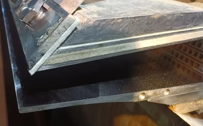
The gap between the lip plate and the breast roll
it refers to the distance between the back of the lower lip plate and the upper roller surface of the breast roll, as shown in the figure below:
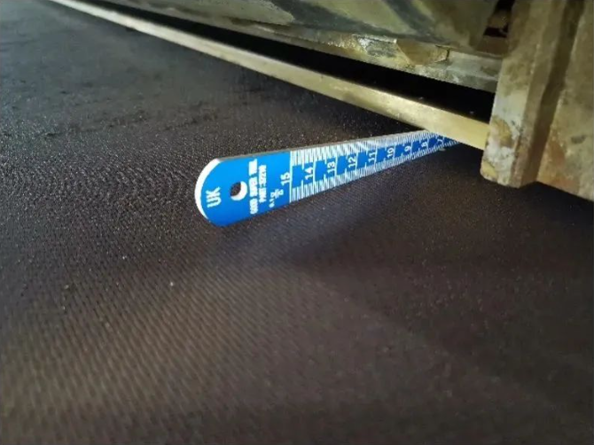
The conventional design of the gap between the lip plate and the breast roll of general paper machine suppliers is generally 5-10 mm. Too large or too small gaps between the lip plate and the breast roll will cause various problems.
Too large a gap will cause the injection angle to become larger, thereby changing the fiber arrangement, allowing more fibers to be arranged in a vertical direction instead of a flat direction, thereby reducing the horizontal interweaving of fibers and reducing the strength of the paper.
Too small a gap between the lip plate and the breast roll will cause the breast roll belt to rotate, forming a suction vacuum, which will easily peel off the dirt on the back of the lower lip plate, falling off on the paper surface and the mesh table, causing treatment or paper breakage.
In addition, the gaps between the breast roll and the lower lip plate must be consistent on both sides, that is, the gaps on the operating side and the transmission side are consistent.
From experience, when the gap deviation exceeds 0.2 mm per meter, it may cause obvious inconsistency in the points of the two ends.
The upper lip plate protrusion distance
It (S value as shown in the figure below) refers to the distance of the lip plate strip installed on the upper lip plate beam. The design values of this distance vary greatly from different equipment suppliers but are generally between 1-10mm. Here, the concept of an inclination angle is also extended, that is, the angle formed by the inner side of the upper lip plate strip and the slurry flow surface of the upper lip plate beam.
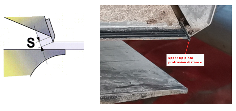
The upper lip plate of the headbox is designed to protrude the upper lip plate beam. In order to effectively interfere with sizing and facilitate local fine-tuning of the quantitative, the protrusion distances for different headboxes are inconsistent.
From the earliest design, the protrusion distance is generally large, ranging from 3-5mm to 8-10mm.
However, with the passage of time, technical updates, and experience, it was found that excessive protrusion distances and too small inclination angles will form obvious turbulence and vortices on the inner side of the lip plate, thereby affecting the arrangement of fibers. Therefore, the design protrusion distance of the later headbox is significantly smaller, and the inclination angle is larger because the state of the pulp flow ejected from the headbox is more stable and ideal.
For the same headbox, it is not recommended to easily modify the protrusion distance, because if the changed protrusion distance is operated according to the conventional lip opening display, it will directly affect the sizing amount and thus change the uniformity.
For example, during normal production, the lip opening is generally controlled at 10 mm. If the probe distance is changed, for example, the actual probe distance becomes smaller, and the actual lip opening becomes larger after the machine is turned on, it will be found that the uniformity becomes better, but the water content becomes larger, and it is difficult to dehydrate.
On the contrary, if the probe distance becomes larger, the area on the inner side of the upper lip plate that bears the slurry pressure becomes larger, which may cause slurry leakage.
Therefore, when the lip needs to be fine-tuned locally during production, it is not recommended to adjust it frequently in one direction.